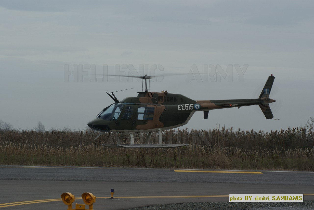
Agusta-Bell 206B RC Helicopter in Scale 1:5.7 of the Greek Army Aviation


Introduction

I have started this blog as an english-text alternative to a thread that I have opened in modelclub.gr (modelclub forum in greek) regarding my project to build an RC scale model of an Agusta-Bell 206B Jet Ranger II of the Hellenic Army (see unofficial site).


Now a few words about the project itself. The model is based on the fuselage provided by Vario (model 1004) in scale 1:5.7. There are very little differences between a Jet Ranger III (model kit) and an Agusta-Bell AB-206B Jet Ranger II that I needed for the project, so I decided to get the kit from Vario. The kit has been bought from one of the best specialists and professionals in the field, Mr Thomas Baumann who has helped me with making my choice of the model and its accessories (Helikopter Baumann). Thanks Thomas! I would also like to thank the team of eflight for their professional support not only for this construction but for all my RC models and accessories. In addition, I would like to thank the team from Innoflyer and especially Mr. Christophe Raible for the help with the lighting system and for letting me test a new CPL model before its official launch. I would like to add here the biwix.com RC helicopter store and Johnny Trolliet at my hometown Renens for his exceptional service, availability and prices!

The particularity of this project is that the mechanism that I fit in the fuselage is not the one from Vario but a modified Align T-Rex 700E (Align RC Helicopters). I will give here details on the way that this is done with diagrams, photos, tips and tricks. This will cover the first part. The flight tests of the modified T-REX 700E have been conducted at the RC model field in Dizy, Switzerland that belongs to the Dizy RC Modelling Group (GAM Dizy). Big THANKS to all the members of the Club for the great friendliness since the first day I started there and for their help with advice and tips!

The second part will be dedicated to the scale model itself. Some photos of the Greek AB-206B can be found on the internet but they do not cover all the details. More photos of the aircraft with the Greek colors may be requested in the forum of modelclub.gr where I have gotten most of them thanks to the team spirit and great friendliness of the members (THANKS^1000 dsamba!!!). In order to complete the photographic part of the project I managed to get my own photos of a Jet Ranger III. This has been made possible thanks to the courtesy of the people from Heli-Lausanne (Heli-Lausanne) who have immediately accepted my request to get there and take as many photos as I needed. A big THANKS to them too!!!
At the last phase of construction, I have got invaluable help for the dimensions of the AB-206B landing gear from Iraklis Karailidis. Many-many thanks to you Iraklis!

So after this short introduction I will start publishing the steps I have already taken and will take during this quite challenging project (at least for me, it is my first scale RC helicopter).

I hope that you will find this blog helpful if you have a similar (or the same) project as mine and you will enjoy it as much as I do!

Welcome!
Hellenicopter

04/02/2014

Landing gear: made from scratch.

 NEW UPDATES, SEE BELOW!

After more than 2 months of silence I come back with some news on this project. It took a lot of time to come up with a reliable solution for the skids of the helicopter.

The original legs and skids from Vario are just... wrong in terms of geometry (are you listening Vario developers?). My experienced friends at GAM Dizy told me that this is not the only Vario model that has this weakness. Nevertheless, the quality of the kits in general is quite good but there is always a lot of place for improvements, especially when it comes to the scale details and looks.

As you can see in the photos hereby the legs form a 60-degree angle with the horizontal plane when looking face-to-face the helicopter and also they form a 10-degree angle with the vertical direction towards the front when looking from the side.

The helicopter that I have to reproduce also has floats in lieu of normal skids that had to be done from scratch as the legs.


The legs are made of anodized aluminum tubes with 1.2cm external diameter and the floaters of 0.8mm-thick aluminum sheet. Bending, drilling and the final mounting of the tubes was difficult because it is difficult to bend the tubes to the desired angle without creating a notch. I have made a tube-bender from scratch using iron pulleys, a bending-spring and some other common hardware (I will cover that in another article).

Drilling of the holes for mounting the legs on the previously mounted wooden frame is done using a press drill machine using a 10cm-wide disc made of resin. A Tupperware cap has been used as a mold. A carpenter's laser pointer has been used in order to turn the legs to the right angle (10 degrees) for drilling. The disc has given increased precision in reading the angle due to the relatively large diameter. A 10-degree angle corresponds to approximately 1cm on the periphery of the disc that is easy to read with a good precision. If I had to do that on the outer surface of the tube than I would have to precisely read and mark a 1mm-distance - out of the question with only 0.5mm available precision!


The next step was to build the floats. Stereometry has also been needed here in order to calculate the points and directions of bending of the aluminum sheet. The foil has been cut using a common cutter and by taking advantage of the material fatigue after indenting 5-6 deep grooves into the sheet and then bending it back and forth it is cleaved exactly along the groove (see images).


Each float has two cuts, one at the front and another at the back. Those cuts have been soldered using Durafix rods and a torch. The important detail when using Durafix is to prepare well the surface by rubbing it with a steel brush to remove alumina (oxide) and then attach the parts to solder on a big ceramic plate or cement brick (as I did) with iron fasteners. This limits down to a minimum any thermal losses and you can solder within seconds even with a moderate single-gas torch.


The photos below show the almost final result. Still the attachments of the legs to the floats are not finished but you can get an idea of the geometry and the relatively good fit. Nevertheless, the radius of curvature of the legs is still not perfect as it should be around 7-8cm instead of 5cm (radius of the bending pulley). Maybe when I have more time I will correct that by building new legs but for the moment the geometry is acceptable and much better than the geometry of the kit's landing skids.


As you can tell from the photos above, the doors are already mounted. I have modified the Vario locking mechanisms and adapted them to the scale looks of the model as the door handles of the real helicopter are located at the center of the door. Here is a photo of the modification:


Also I have made quite some progress with the navigation lights. I have chosen the solution from Innoflyer and I am very glad for that. The quality of their products is very good, the intensity of their LEDs is blinding (really one has to pay attention not to look directly at them!) and the people running the company are very professional. I had the chance to get one of their prototypes before the official launch of the product. This LED is a CPL and has the ideal shape and dimensions for the tail position light (see image below). Many thanks to Mr. Christophe Raible from Innoflyer for letting me having this superb prototype for the needs of my model!


I am planning to start building the engine exhausts. I will use an expanded polystyrene model to build a mold and then laminate with carbon fibers as I have already done for the tail hub cover (see below).


That's all for the moment. I will post details on the dimensions of the landing gear, how to bend the tubes and the aluminum sheet a bit later this month along with other stuff while the project progresses.

Cheers!

UPDATE
As I said before the radius of curvature of the legs is not as long as it should for the scale. I decided to correct this.
 

I changed the wheel/pulley used for bending. Now the pulley that I used before for bending is used on the lever and it has been replaced by a wheel (red, see photos) with 9cm of radius. A draft for the new leg geometry is attached as pdf on the right-hand side of the blog (see links).

Aluminum tubes with thin sidewalls and especially when they are anodized are easy to crack under tensile stress, which renders bending a bit tricky. What is important is to use a spring for bending with an internal diameter exactly equal to the outer diameter of the tube to bend. The spring offers an excellent support for the sidewalls of the tube inhibiting as much as possible the distortion of the cross-section shape (from cricular to elliptical). I used it together with the bending machine that I made from scratch. The result is very satisfying and now I only have to repeat the drilling exercise as I described before. I hope that this week I will have the landing gear finished.
The second very important detail when bending tubes is to inhibit any sliding of the tube while bending. Otherwise the result will be at least not good and in the worst case you will end up with a notched tube instead of a bent one.

In one of the photos here you can see that I use two rings that are attached firmly at the back of the tube in order to avoid sliding while bending. It works very well and the plasticity is distributed over a long curve instead of a single point (notch). Nevertheless, due to this plasticity the anodized surface becomes slightly cracked due to the tensile strain on the outer side of the curve. This is visible to the naked eye as the color of the tube around that region becomes slightly lighter (from medium grey to light grey). Nothing so alarming as the tube cross-section remains almost the same (slide-stop rings can be pulled through the bend region almost without effort).
There is only one remaining obstacle: the linkage of the legs with the floats. This is still a small headache, I want to make it simple, light and, of course, reliable! I already have an idea how to do it and I will try it with my new CAD tool that I find excellent for amateur design work: TurboCAD. The license costs more or less the same money as a stupid Wiindows 8 copy but is millions of times more reliable and useful.
Parenthesis: I am a Mac user since the age of 15 - system 6.0.7 for those who know - and by definition not 100% objective, but, frankly, I have never seen a worse OS than Windows 8 since then; we should be paid for taking it off the shelves not paying for it!!!

I will  post some more on the landing gear and maybe the lighting system this week, or at least I hope I will find the time.

Cheers!

UPDATE 2

I have found some time to remake the landing gear legs  with the new tool and mount them on the heli.
Here are some photos. I still have to make the attachments to the skids (and I am still scratching my head how...).


Here are two photos (real and model) for comparison, it's not bad:

That's all for the moment.

Bye!

29/11/2013

I continue with some details already published on modelclub.gr.

Here are some photos showing the tilt of the main shaft as well as the point of exit from the fuselage. They look quite OK with the scale (I remind you that the shaft is not the original shaft from Align but a customized shaft from Vario - see pdf).


One more photo showing the position of the front part of the skids legs with respect to the fuselage.


Another photo from inside with the Trex mechanics mounted.


Other stuff from the same site: the engine cowl with the openings for cooling. The round opening on the side has been made with a 0.8mm drill and a printed pattern on auto-adhesive sheet. I realized later that the pattern is not correct as it is rectangular instead of rhombic. I will have to correct it. There are also photos showing the real opening and the dimensions of this round opening. On the top there are two round-shaped openings. The estimated size is given. The openings are cut to the proper size for the scale but they are not very well positioned as I found out later and I will also have to correct that.


07/11/2013

A few days ago I have published a pdf regarding the basic modifications I have made to the mechanics of the Trex 700E in order to install it in the Vario Jet Ranger fuselage. Here I elaborate a bit some steps that presented some difficulty.

The Tail Boom

In general, the Trex mechanics fit surprisingly well into the Vario fuselage. The main difficulty is the tail boom and the hub. Initially, I have tried to use the upgrade available by Align to convert a Trex 700E to an 800. Unfortunately, this doesn't work, the boom and the shaft are 3-4cm too short. I had to buy in addition a Trex-800 tail shaft. It is difficult to find aluminum tubes in the raw-material market with the right cross-section dimensions so you have to put together the tail boom from the upgrade with an extension that is cut off from a second tube (available from the original Trex-700E kit). I have tried to use a CF tube but it was not easy because the cross-section was not wide enough. I think that Align has chosen on purpose to use tubes with those non-standard cross-section dimensions in order to be forced to buy their tubes...

In my case, I have decided to merge the two boom parts towards the frame side and not the hub side. This is done because at the frame side it is much easier to put them together in a reliable way. A 20mm aluminum tube is used to merge the two boom parts from the inside without creating any problems to the shaft. The small part has been glued with epoxy glue to this tube (with Devcon 30min, still the best out there, much better than the 30min Zap epoxy) and the long full-length boom has been screwed on it with two short M4 screws (see picture in pdf). The short boom piece resides safely in the plastic gear box at the back of the Trex's CF frame. The long boom part is partly inside the same gear box.


The boom parts have to be assembled and secured before installing the mechanics at their final position.

Securing the Lynx rods to the boom before final installation of the mechanics in the fuselage.

Tightening the screws at the rear of the plastic gear box.
In brief, this solution works fine but I would prefer to have a full length tube instead. Unfortunately, although the Trex-800 boom has the right length, it is too large (25mm cross-section) to go through the fuselage's tail and doesn't do the job (I would have to change the plastic gear box and the tail hub too).  In addition, the Lynx Heli Innovations tail boom mounting rods (cut to the right length) have helped a lot to add stability. Those rods come already glued and screwed to their aluminum anchors and it is difficult to unglue them in order to adjust their length (you need a hot-air pistol at around 200 degrees Celsius and a lot of patience!).


Gluing back together the aluminum anchors to the tail boom mounting rods.


Connecting the boom to the fuselage

The connection of the GF (glass fiber) tail boom to the fuselage has been modified in order to be able to pass through it the Trex's tail tube. Two multi-layer 5mm-thick plywood plates have been glued on each side (fuselage sied and tail side). On the tail side two M5 drive-in nuts have been used for screwing the two parts tightly together (see pictures below).


The Tail Hub


The second "headache" has been the mounting of the tail hub. The tail of the fuselage already provides a quite big opening and it is almost perfect for the installation of the Trex-700E hub. Well, almost... I had to cut out a small opening for the hub's tightening screws as you can see in the picture below. This is a necessary "evil" as there is no other way to fit the hub. In the final assembly the metallic part of the hub barely overhangs out of the fuselage. In the real helicopter this part of the tail is covered by a canopy from above that is held with numerous screws on the body of the tail (see pictures below). So there is still place for hiding this with such a canopy made of glass-fiber or carbon fiber and held in place with screws as well (see photo below of a CF cover I made).
Picture showing the opening in the GF part of the tail to accommodate the tail hub.

Tail cover made of CF and epoxy. The lighter the better in order to avoid adding too much weight on the tail.


Finally, in order to better integrate the hub in the fuselage an aluminum plate has been made (1.5mm-thick) in order to screw the hub on the fuselage (see following pictures).


In order to avoid bad surprises and to reinforce the fuselage around the hub I laminated the internal surface of the fuselage with one 3K carbon-fiber sheet. In this way there is much less risk for the screws holding the plate and the hub to crack the fuselage and finally break it due to vibrations.